Essential Safety Tips for Handling a High Voltage Electric Vehicle Battery
Electric and Hybrid Vehicles
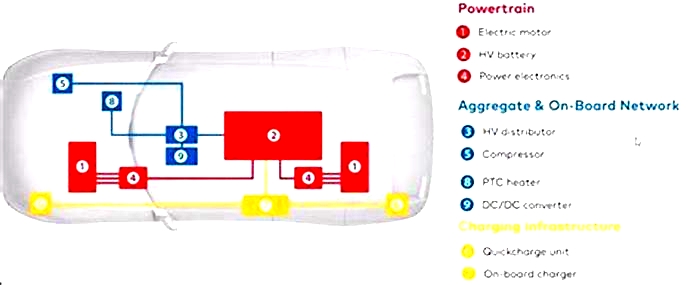
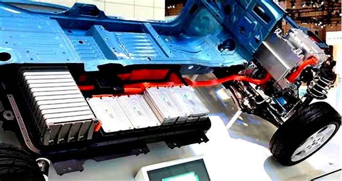
Battery-electric vehicles use battery packs to store energy and utilizes the electric motor to move the vehicle. These battery packs could last the lifespan of the vehicle, but there are many factors that could affect how long a battery lasts, according to FuelEconomy.gov and predictive modeling by the Department of Energy's National Renewable Energy Laboratory.
Most modern electric vehicle battery packs employ some form of lithium-ion chemistries, such as NMC (Nickel Manganese Cobalt) or NCA (Nickel Cobalt Aluminum); these battery chemistries use more costly materials that offer greater driving range. Another lithium-ion chemistry, Lithium Iron Phosphate (LFP), uses less costly materials that offer a moderate range with a longer cycle life.
Batteries and Temperature
EV battery packs include interconnected cells, hardware, and software to manage the batterys operation; this is referred to as the battery management system. Temperature control is important for batteries, as extreme temperatures can affect performance and shorten a batterys lifespan. Thermal management systems keep the batteries within the pack at an optimal temperature even in harsher environments but this can negatively affect your driving range since some of the batterys energy is used for thermal management instead of motor use.
Battery and Flooding
Batteries in hybrid and electric vehicles are highly corrosive and should not be exposed to standing water. Flooded vehicles lead to high-voltage shock hazards, which could lead to a fire. If your EV has been exposed to flood conditions and you suspect your battery is damaged, contact your dealer and/or emergency services.
Charging
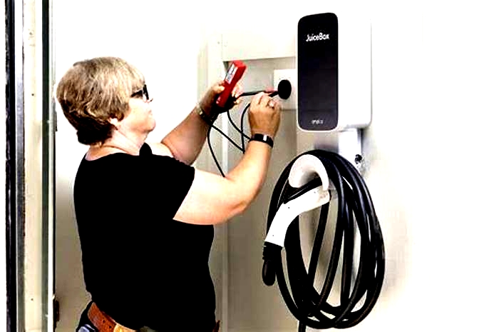
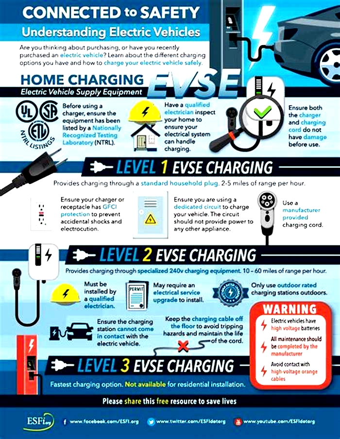
Today, many electric vehicles have a driving range of around 300 miles on a full charge, while some have a driving range upwards of 400 miles on a single charge. When the batterys charge is low, the EV needs to plug into an electric power source to replenish the batterys charge this can occur at home, work, or any other public location along your route. However, not all vehicles and charging stations charge at the same rate. DC fast chargers can replenish your batterys charge in under an hour, while at-home chargers may take all night to recharge your battery.
Always follow the owners manual and the manufacturers instructions regarding charging safety protocols, maintenance requirements, and related operations.
Charging Resources
Before driving an EV, its important to familiarize yourself with charging stations their level of charging, plug type, and location. The U.S. Department of Transportation offers more information on electric vehicle charging speeds and plug types. Understanding EV chargers and knowing their locations along your route will help you plan when driving an electric vehicle. The U.S. Department of Energy offers more information on electric vehicle charging station locations.
Handling Lithium-Ion Batteries in Electric Vehicles: Preventing and Recovering from Hazardous Events
Today, fixed fire detection and suppression systems are common for heavy vehicles with combustion engine compartments. These systems have shown to limit the consequences of fire. Examples of this include the reconstruction of a fire involving two gas buses by the Swedish Accident Investigation Authority [47] as well as an investigation by the Australian Office of Transport Safety Investigations (OTSI) [48]. They found that without effective fire detection and suppression, achieved by fixed systems in the engine compartment, similar events could be catastrophic. Assuming that a LIB fire is detected and there is access to the inside of the LIB pack(s), integrating a fixed fire suppression system inside the LIB may prove useful in preventing (further) failure and recovering from a thermal runaway event, as well as providing time for evacuation. Andersson et al. [49] found that agents with a high heat capacity, such as water and low expansion foam, provide rapid cooling and fire extinguishment for a battery. Other agents they tested, such as high expansion foam and nitrogen gas, provided less cooling but could still extinguish the flames if introduced into the battery pack correctly. Note however that these tests considered LIBs on ships and thus large quantities of suppressant were available. The capacity of fixed suppression systems on road vehicles is much more limited, however.
5.1 Test Setup
Fire suppression tests were performed by RISE during 2019 on traction batteries for heavy vehicle applications shown in Fig.8 [50]. The goal of these tests was to evaluate the performance and applicability of commercially available fixed fire suppression systems in controlling thermal events within this battery. Important parameters here are the limited amount of suppression agent available on the vehicle, the suppression system activation time and duration, and position of the nozzles.
The battery pack consisting of two layers placed inside the test container. The burner used to initiate thermal runaway is also shown
For the purpose of these tests the traction battery was modified to fit a combination of dummy and live battery modules. Each live battery module contains 12 hard prismatic cells (anode/cathode: C/NMC, nominal voltage: 3.7V, rated capacity: 28 Ah). In all tests the state of charge was 100%. The dummy battery modules were made of stainless steel, filled with sand, and sealed. Modifications include removal of other combustibles in the battery pack such as connection cables and feedthroughs. A small opening in the body of the battery pack was made to expose a battery cell directly to the gas burner. A photo of the initial test setup is seen in Fig.8. The traction battery consisted of two layers. Early on it was determined that the risk for fire propagation from the upper to the lower layer was very low, hence the following tests were conducted using only the upper layer, as can be seen in Fig.9.
The second battery pack layer was removed for the remaining tests. Here the hoses connecting to nozzles inside the battery pack are also shown
Seven tests were performed as shown in Table3, two free-burn tests, one external fire suppression test, and four internal fire suppression tests. Up to 13L of suppressant was used for all suppression tests, as is typical for fire suppression systems installed on heavy vehicles. The commercially available systems that were considered both employ water-based suppression agents with less than 5% foam additives.
5.2 Measurements
Temperatures inside the battery pack were measured with type-K thermocouples. These thermocouples, seen in Fig.10, were either welded to the modules to measure surface temperatures (TC1-TC13) or positioned to measure gas temperatures (TC14 and TC15) inside the battery pack. Those thermocouples measuring gas temperatures were positioned at the same height as those welded to the modules, at half the module height. TC1 was fixed to the traction battery surface from the inside, 5cm below the opening for the gas burner. All thermocouples were positioned at the same spot for all tests, meaning that only 15 thermocouples were used in test 27.
Overview of measurement points and their position with respect to the live battery modules and cells
The sides of the live battery modules consist of sheet metal, which is where the thermocouples were attached. The cell number closest to each thermocouple are also listed in Fig.10. The gas burner was positioned so that the flame impinged on cell no. 6 of module no. 1.
5.3 Water Mist System
The water mist system was considered during test 2 (mist 1) and test 3 (mist 2) and is shown in Fig.11. The suppression agent was stored in and supplied by 6.5L piston accumulators, each weighing 18kg. Full cone nozzles were used inside the battery pack with a flow rate capacity of 1.7L/min and a 60 spray angle. According to the manufacturer, these nozzles produce a droplet size of approximately 50m in diameter. Three nozzles were considered in mist 1. These were connected to the 26.5L cylinders, whereas in mist2 these three nozzles were connected to only one 6.5L cylinder. In addition, a fourth nozzle was aimed at the initiating module and was connected to its own 6.5L cylinder. The total amount of suppressant was thus the same in the two tests (13 L) yet the number of nozzles and their spray duration differed. For mist 1 this was about 3min while for mist 2 these nozzles were active for 1.5min while the fourth nozzle continued spraying for an additional 2.5min, i.e. 4min in total.
The water mist system considered for mist 1 and mist 2. (a) The two 6.5 L piston accumulators that supply the suppressant; (b) overview of the nozzle placements; (c) nozzle placement near the initiating module in mist 2; (d) nozzle placement between dummy modules; (e) nozzle placement on the far side of the traction battery
5.4 Water Spray System
The water spray system was considered during tests 5, 6, and 7 and is shown in Fig.12. In this case, one single piston accumulator with 12.5 L of suppressant, weighing 32.2kg, was used to supply all nozzles. These nozzles were also full cone nozzles although with a smaller size and a high flow rate of 7.2L/min at an 80 spray angle. In test 5 (spray ext), external suppression, a total of three nozzles were positioned 0.4m above the traction battery. Two of them were aimed at the initiating side of the pack whereas a third one was aimed at its other end. In test 6 (spray 1) and test 7 (spray 2) these three nozzles were installed inside the traction battery. Two nozzles came loose in spray 1 which resulted in suppressant not making it into the pack. As such, the exact same setup was used for spray 2. This system released the agent in about 30s.
The water spray system considered for spray ext, spray 1 and spray 2. (a) The external fire suppression system; (b) overview of the nozzle placements; (c) nozzle placement near the initiating module; (d) nozzle placement between dummy modules; (e) nozzle placement on the far side of the traction battery
5.5 Test Results
Thermal runaway was initiated in one battery module by impinging on one of its cells with the flame of a gas burner. When thermal runaway was observed, as shown in Fig.13, the gas burner was immediately shut off. In all fire suppression tests, the systems were activated 30s after this initial thermal runaway event. This time was chosen as to simulate a delay between the fire starting and it being detected by a fire detection system. It took roughly 20min to initiate thermal runaway, except for mist 2 where 54min were needed due to a slight difference in the position of the impinging flame. Temperature recordings however showed nearly identical temperatures within the battery pack, regardless of pre-heating time. This suggests that the initial time period and temperature had minor influence on the scenario after the trigger cell went into thermal runaway. The tests were terminated when there was no longer any sign of thermal activity and recorded temperatures on the target module were stable and below 80C.
Thermal runaway event during test 1 (ref 1). This occurred after the flame impinged on the initiating module for roughly 20min
External flames were visible in the reference tests, i.e. without fire suppression, for roughly 20min after the initial thermal runaway event. When external or internal suppression were introduced however these flames were knocked out quickly after it activated, see Fig.14. This is somewhat positive from a fire hazard perspective, as a potential initiating hazard is removed. However, activity proceeded inside the pack and a large amount of gas was produced. If allowed to accumulate in an enclosed space, there is a risk for a gas explosion due to sparks from the battery or other potential ignition sources.
(a) External flames were quickly knocked out after the external fire suppression system activated; (b) succeeding thermal runaway events produced a lot of gas
Cooling inside the battery pack was insignificant if suppressant was applied externally to the pack, see Fig.15a. This was also seen when succeeding thermal runaway events in the initiating module were studied, see Fig.15b. The internal application of the suppressant had a positive impact on reducing the risk for fire propagation between modules inside the tested battery pack. It also delayed how quickly the fire spread from one battery cell, or thermally propagated, to the next cell inside the initiating module. In addition, thermal runaway reactions were not triggered in all cells within this module either.
(a) Comparison of measured temperatures in the free-burn tests and external fire suppression; (b) number of cells inside the initiating module that went into thermal runaway (based on visual observations)
Thermal runaway did not initiate outside of the initiating module in any of the tests, i.e. there was no thermal runaway propagation from the initiating module to other modules within the battery pack. However, the registered temperatures without fire suppression were still high enough to cause irreversible damage. Considering a threshold temperature of~200C (temperature at the external surface of the module) for triggering thermal runaway, internal suppression systems a potential to stop thermal runaway propagation as seen from Fig.16. It shows great promise that this can be achieved with only 13 L of suppressant as long as there is access to the contents of the traction battery. With the threshold value in mind, there will be no propagation from the initiating module to its neighbour, as represented by TC8 in Fig.16.
Temperatures measured on the two live modules
While internal application of a water-based fire suppression system had a good potential to have a lasting cooling effect on the traction battery and to increase the chance of mitigating and preventing cascading failure, external suppression was not as effective. Still, it did knock out appearing flames, which means that this method is still useful in preventing fire spread from the battery to the surroundings. However, as it did not cool the traction battery, thermal activity was not halted, and large quantities of gas continued to be released. If these gases accumulate in enclosed spaces, such as the traction battery itself, there is a risk for explosion due to piloted ignition, e.g. sparks from batteries or hot surfaces.
Table4 gives an overview and comparison of the results obtained in this study. The number of cells that went into thermal runaway is presented in the second column for each test. None of the tests were able to prevent thermal propagation throughout Module 1, however the internal fire suppression systems indicate a positive effect as some cells were saved. This trend was also found when looking at the average propagation rates. The average propagation rate refers to the time it takes for thermal runaway to propagate in order of successive failure, i.e. from the 1st to the 3rd, 3rd to the 6th and finally 6th to the last cell. These rates were reduced through consideration of internal fire suppression. The external fire suppression system had some effect, yet differences may be too small compared to the reference tests to be considered significant.
The water mist system performed slightly better at hindering cell to cell propagation than the water spray system. In addition, the water mist system was able to restrict temperatures on both sides of Module2. The water spray system had a positive effect on the side facing towards Module 1 but was less effective at cooling the other side of Module2. A reason for this could be the difference in release time of the agents. Specifically, 30s for the water spray system and up to several minutes for the water mist systems. This possibly affected the amount of water that could be vaporized inside the pack. Another potential cause may be related to the agent contents and the difference in droplet size between a mist and a spray. However, the cooling effects of both systems were significant. For other scenarios and/or batteries, this difference might be crucial to avoid cascading failure in battery packs.
During the water spray tests it could be observed that large quantities of suppressant was thrown out of the battery pack, likely due to the short activation time and the limited space inside the battery pack. This suggests that a low flow rate and a longer release time is preferable, as was seen from the tests since the water mist system provided a stronger cooling effect throughout the traction battery. The test results do not show the minimum amount of suppressant needed to achieve a cooling effect, but 1213 L achieved good results here. As a lot of suppressant was lost in the water spray tests, similar results would probably have been achieved if a smaller piston accumulator was considered.
There were no apparent benefits over introducing direct application of the fire suppressant onto the initiating module. It gave similar results in terms of propagation rates, surface temperatures and gas temperatures within the pack. These tests showed that internal total flooding of the battery pack, preferably at a low flow rates and long release times as mentioned, is most effective at hindering cell to cell and module to module propagation.
A post-test damage assessment was done 3days after the fire tests were performed. This wait period was considered to ensure the traction battery was stable before it was opened. Analysing the two live modules after each test confirmed that the fire did not spread to the neighbouring module in any of the tests. One thing to keep in mind, however, is that there may still be a risk for cells (re)igniting after some time. If there are energized cells in the battery pack, that have sustained abuse or damage, this risk remains. For these tests, there was no reignition up to 3days after the first test was performed.

